AT Command Tester is an free online software tool that can be used to test all features of Huawei modules. Since the software tool is browser-based, it can be used on all common PC-based browsers (Chrome, IE, Firefox, Safari) and works on popular operating systems (Windows, Linux, Mac).
How to connect to Huawei module?
Typically module is hosted on some target platform (host platform or hardware development kit (HDK). Once the target platform is connected to the PC through a USB or serial cable and the drivers are installed, the module ports are avaialble on the PC as shown below. Depending on your module and the drivers, the port names might be listed differently.
AT Command Tester is an free online software tool that can be used to test all features of Huawei modules. Since the software tool is browser-based, it can be used on all common PC-based browsers (Chrome, IE, Firefox, Safari) and works on popular operating systems (Windows, Linux, Mac).
“>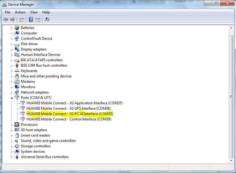
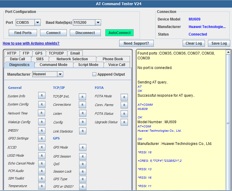
On the AT Command Tester tool, ‘Find Ports’ will list all the available serial ports. Connect to the port that maps to ‘PC UI interface’ as shown above. Other option is to do ‘Autoconnect’ AT Command tester will automatically find and connect to the connect to the appropriate port of the Huawei module. If the connection is successful, the model number and connection status will be shown as below,
Diagnostics Commands
In the ‘Diagnostics Command’ tab, information related to the device and the network can be easily queried from the device. To send Huawei module specifc diagnostics queries, select the ‘Huawei’ drop-down selection inside the ‘Diagnostics’ tab.
//Get the module manufacturer

AT+CGMI
Huawei Technologies Co., Ltd.
OK
Manufacturer : Huawei Technologies Co., Ltd.
//Read the model number
AT+CGMM
MU609
OK
Model Number : MU609
//Get the revision number
AT+CGMR
12.105.29.00.00
OK
Revision : 12.105.29.00.00
//Get the device capabilities
AT+GCAP
+GCAP: +CGSM,+DS,+ES
OK
Device supports following features:GSM,Data Service,
//Device profile
AT&V
&C: 1; &D: 2; &S: 0; E: 1; Q: 0; V: 1; X: 1; S0: 0; S3: 13; S4: 10;
S5: 8; S7: 0; S10: 14; +ICF: 3,3; +IFC: 0,0
OK
//Get the battery status
AT+CBC
+CBC: 0,61
OK
Device is powered by battery.
//Device functionality
AT+CFUN?
+CFUN: 1
OK
Device has Full functionality.
//Device status
AT+CPAS
+CPAS: 4
OK
Call in progress.
//Device clock
AT+CCLK?
+CCLK: “1980/01/06,00:43:58″
OK
Current time is”1980/01/06,00:43:58”
//Get the device serial number
AT+CGSN
35778404xxxxxxx
OK
//Character set used by the module
AT+CSCS?
+CSCS: “IRA”
OK
Character set used by Terminal Equipment is “IRA”
//Indicators available from the module
The following indicators types are supported by the device,
AT+CIND=?
+CIND: (“battchg”,(0-5)),(“signal”,(0-5)),(“service”,(0-1)),(“call”,(0-1)),(“roam”,(0-1)),(“smsfull”,(0-1)),(“GPRS coverage”,(0-1)),(“callsetup”,(0-3))
OK
The indicator values are,
AT+CIND?
+CIND: 3,4,1,1,1,0,1,0
OK
//Get the GPRS class supported by the module
AT+CGCLASS?
+CGCLASS: “A”
OK
//Check if any PDP context has been activated
AT+CGACT?
+CGACT: 1,1
+CGACT: 15,0
OK
Device is connected.
//Get the IP address of the connected PDP context
AT+CGPADDR= 1
+CGPADDR: 1,””
OK
IP Address of the connected profile is “”
//Get the list of PDP contexts stored in the module
AT+CGDCONT?
+CGDCONT: 1,”IP”,”bluevia.movistar.es”,”0.0.0.0″,0,0
+CGDCONT: 15,”IP”,”bluevia.movistar.es”,”0.0.0.0″,0,0
OK
Following connection profiles are available,
CID-> 1
PDP Type->IP
APN->bluevia.movistar.es
PDP Address->0.0.0.0
Data Compression->0
Header Compression->0
CID-> 15
PDP Type->IP
APN->bluevia.movistar.es
PDP Address->0.0.0.0
Data Compression->0
Header Compression->0
// Check if the device is attached to the network
AT+CGATT?
+CGATT: 1
OK
Device is attached to the network
//Bearer configuration
AT+CBST?
+CBST: 0,0,1
OK
Speed ->autobauding
Bearer Service -> Data circuit asynchronous
Connection Element -> Non transparent
//Radio Link Protocol (RLP) paramerters
AT+CRLP?
+CRLP: 61,61,48,6,0
+CRLP: 61,61,48,6,1
+CRLP: 240,240,52,6,2
OK
Radio Link Protocol (RLP) Configuration paramaters:
IWF Window Dimension ->61
MS Window Dimension->61
Acknowledge Timer->48
Retransmission Attempts->6
Protocol Version->0
AT+FCLASS?
0
OK
The device is configured for data
//USSD configuration
AT+CUSD?
+CUSD: 0
OK
//Service reporting
AT+CR?
+CR: 0
OK
Service reporting control is disabled
//Extended error reporting
AT+CEER
+CEER: No cause information available
OK
//Signal strength
AT+CSQ
+CSQ: 23,99
OK
Signal level is -67 dbm. Signal condition is excellent.The signal strength range is -53 dbm (Excellent) to -109 dbm (Marginal).
//Current network operator
AT+COPS?
+COPS: 0,0,”AT&T”,2
OK
Device is currently on “AT&T” network.
//Registration status
AT+CREG?
+CREG: 2,5,”7CF4″,”232B51B”,2
OK
Device is registered and is roaming.
//Get the available networks
AT+COPS=?
^RSSI: 19
Please wait as this could take sometime….
^RSSI: 24
+COPS: (1,”AT&T”,”AT&T”,”310410″,0),(1,”T-Mobile”,”T-Mobile”,”310260″,2),(1,”T-Mobile”,”T-Mobile”,”310260″,0),(2,”AT&T”,”AT&T”,”310410″,2),,(0,1,2,3,4),(0,1,2)
OK
//Preferred operator list
The preferred operator list:
AT+CPOL?
OK
//SMS mode
AT+CMGF?
+CMGF: 0
OK
SMS message for is configured for PDU mode
//SMS service center address
AT+CSCA?
+CSCA: “+34609092815”,145
OK
SMS service center address is “+34609092815”
//SMS support
AT+CSMS?
+CSMS: 0,1,1,1
OK
Service-> GSM 27.005 Compatible
Mobile Terminated SMS -> Supported
Mobile Originated SMS -> Supported
Broadcast SMS messages -> Supported
//SIM card status
AT+CPIN?
+CPIN: READY
OK
SIM is ready.
//Sysinfo is a very useful AT command that provides info about the network.
AT^SYSINFO
^SYSINFO: 2,3,1,5,1,,4
OK
Serving Status -> Valid Services
Serving Domain -> PS+CS Service Only
Roaming Status -> Roaming
System Mode-> WCDMA Mode
SIM State -> Valid SIM card
System submode -> WCDMA Mode
AT^SYSCFG?
^SYSCFG: 2,2,3FFFFFFF,1,2
OK
Mode -> Automatic
Acquisition Order -> WCDMA > GSM
Band -> 3FFFFFFF
Roaming-> Supported
Serving Domain -> PS+CS Service Only
//Get the system time
AT^NWTIME?
^NWTIME: 14/01/14,09:58:20-32,00
OK
Date -> 14/01/14
Time -> 09:58:20-32
Daylight Saving -> 00
//How the module is configured for wakeup?
AT^WAKEUPCFG?
^WAKEUPCFG: 1,3,15
OK
Wakeup Enable/Diable -> 1
Channel -> 3
Source -> 15
//Get the IMEI number of the module
AT^IMEISV?
^IMEISV: 3577840400134908
OK
IMEISV -> 3577840400134908
//GPIO configuration
AT^IOCTRL?
^IOCTRL: 00000,10010
OK
Mapped as GPIO5,GPIO4,GPIO3,GPIO2,GPIO1. ‘0’ is input, ‘1’ is output
Input/Output -> 00000
Value -> 10010
//Get the ICCID of the SIM card
AT^ICCID?
^ICCID: 8934072279xxxxxxxxx
OK
ICCID of the SIM card -> 8934072279xxxxxxxxx
//USSD mode configuration
AT^USSDMODE?
^USSDMODE: 1
OK
Configured for transparent USSD mode
//Echo cancellation for the audio paths
AT^ECHO?
^ECHO: 4
OK
Echo Cancel -> Speakerphone mode, loud echo, long delay
//PCM Audio configuration
AT^CPCM?
^CPCM: 0,0,0,0,0
OK
PCM Working Mode -> MASTER_PRIM
Data Format -> Linear
Clock Signal-> 2.048 MHz
Frame -> Offset cleared
//SIM Tool kit mode
AT^STSF?
^STSF: 1,2
OK
SIM Tool Kit Mode -> STK Active
RawMode -> Standard raw data mode
//Read the temperature
AT^CHIPTEMP?
^CHIPTEMP: 65535,65535,65535,65535,65535,290
OK
The temperature unit is 0.1°C. For example, if the returned value range is (–200,1000), the temperature ranges from –20°C to 100°C.
GSM PA temperature is not supported
WCDMA PA temperature is not supported
LTE PA temperature is not supported
SIM card temperature is not supported
Battery temperature is not supported
Crystal temperature ->290
//Check if temperature protection is enabled
AT^THERMFUN?
^THERMFUN: 1
OK
Temperature protection is enabled
//Get the NDIS connection status
AT^NDISSTATQRY?
^NDISSTATQRY: 0,0,,”IPV4″
OK
Connection Status -> Disconnected
Error code -> 0
PDP Type-> “IPV4”
//Voice call/data call preference
AT^DVCFG?
^DVCFG: 0
OK
Voice call is preferred over data.
//IP configuration status
AT^IPINIT?
^IPINIT: 0
OK
The IP connection is not initialized, or network connection fails to be established..
//Check if any IP connections are opened
OK
No connection has been opened.
//Check if the module is listening to any ports
AT^IPLISTEN?
^IPLISTEN: “”,0,5
OK
Link Type-> “”
Listen Port -> 0
Idle Links -> 5
//Configure IP static parameters
AT^IPCFL?
^IPCFL: 5,10
^IPCFL: 10,1024
^IPCFL: 12,0
OK
Following parameters are configured,
Timer for transparent transmission-> 10
Length of TCP/IP data packet-> 1024
Transmission Mode -> 0
//Get IP data statistics
AT^IPFLOWQ?
^IPFLOWQ: 1,91,91,91,416,416
^IPFLOWQ: 2,0,0,0,0,0
^IPFLOWQ: 3,0,0,0,0,0
^IPFLOWQ: 4,0,0,0,0,0
^IPFLOWQ: 5,0,0,0,0,0
OK
Link statistics information:
Link ID-> 1
Tx from User->91
Tx to Socket->91
Tx Acknowledged->91
Rx from Socket->416
Rx to user->416
Link ID-> 2
Tx from User->0
Tx to Socket->0
Tx Acknowledged->0
Rx from Socket->0
Rx to user->0
Link ID-> 3
Tx from User->0
Tx to Socket->0
Tx Acknowledged->0
Rx from Socket->0
Rx to user->0
Link ID-> 4
Tx from User->0
Tx to Socket->0
Tx Acknowledged->0
Rx from Socket->0
Rx to user->0
Link ID-> 5
Tx from User->0
Tx to Socket->0
Tx Acknowledged->0
Rx from Socket->0
Rx to user->0
//GPS Operation Mode
AT^WPDOM?
^WPDOM: 0
OK
GPS Operation Mode -> Standalone
//GPS positioning setting
AT^WPDST?
^WPDST: 0
OK
Connection Status -> Single position
//GPS QoS
AT^WPQOS?
^WPQOS: 255,50
OK
Performance-> 255 seconds
Accuracy->50 meters
//GPS session lock
AT^WPDGL?
^WPDGL: 0
OK
GPS Session Lock -> Enable Mobile-initiated and Enable Mobile-terminiated session
//Supported GPS types
AT^GPSTYPE?
^GPSTYPE: 15
OK
Following GPS types are supported – Standalone,Control plane,User plane,gpsOneXTRA
//GNSS or GPS mode
AT^WGNSS?
^WGNSS: 0
OK
Positioning system type is GPS
//FOTA mode
AT^FOTAMODE?
^FOTAMODE: 0,0,0,1,7
OK
//FOTA configuration
AT^FOTACFG?
^FOTACFG: “”,””,””,2
OK
APN -> “”
Username -> “”
Password -> “”
Authentication Type -> 2
//FOTA state
AT^FOTASTATE?
^FOTASTATE: 10
OK
FOTA State -> Idle
AT^FOTADLQ?
+CME ERROR: Operation not supported
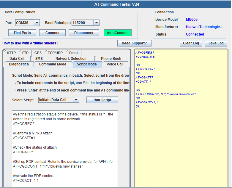
Script Mode
In ‘Script Mode’ you can write script to send batch of AT commands. This is useful to test specific features of the module which requires users to send batch of AT commands.
How to set up data call?
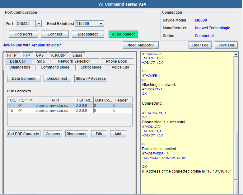
To establish a data call with the Huawei module, an active SIM is required. Then a PDP (Packet Data Protocol) context profile needs to be set up. The profile will contain configuration information for the data calls. The most important field is the APN information. Each network operator has unique APN. You can generally do a google search such as “T-Mobile APN” to get the APN information for your network. In the ‘Data Call’ tab, create a PDP profile for your carrier. Once the profile is created, select that profile and press ‘Connect’ button to connect to that profile. ‘Data Connect’ profile will connect to first avaialble PDP profile.
AT Command Tester tool will check if the device is registered with the network before proceeding with the data call.The intermediary steps are shown in the log window. If the call is sucessful, ‘Show IP Address’ button will display the IP address assigned to the device.
AT Command sequence for setting up data call,

AT+CGDCONT?
+CGDCONT: 1,”IP”,”bluevia.movistar.es”,”0.0.0.0″,0,0
+CGDCONT: 15,”IP”,”bluevia.movistar.es”,”0.0.0.0″,0,0
OK
Following connection profiles are available,
CID-> 1
PDP Type->IP
APN->bluevia.movistar.es
PDP Address->0.0.0.0
Data Compression->0
Header Compression->0
CID-> 15
PDP Type->IP
APN->bluevia.movistar.es
PDP Address->0.0.0.0
Data Compression->0
Header Compression->0
Checking registration status…
+CREG: 2,5,”7CF4″,”2323FEB”,2
OK
Device is registered and is roaming.
Checking if device is already connected…
+CGACT: 1,0
+CGACT: 15,0
OK
AT+CMEE=1
OK
Attaching to network…
AT+CGATT=1
OK
Connecting…
OK
Connection is successful
AT+CGACT?
+CGACT: 1,1
+CGACT: 15,0
OK
Device is connected.
AT+CGPADDR= 1
+CGPADDR: 1,”10.101.10.40″
OK
IP Address of the connected profile is “10.101.10.40”
How to setup Voice Call?
AT Command Tester tool can also be used to test the voice call feature on the module.
In the ‘Voice Call’ tab, both incoming and outgoing voice calls can be tested. For the incoming call, AT comamnd tester will automatically alert the user about the incoming call.
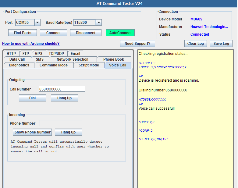
AT Command sequence for setting up voice call
Checking registration status...
+CREG: 2,5,”7CF4″,”2323FEB”,2
OK
Device is registered and is roaming.
Dialing number 858XXXXXXX
OK
Voice call successfull
^ORIG: 2,0
^CONF: 2
^CEND: 2,0,104,127
^RSSI: 18
How to do network selection?
Network selection enables the user to select an available network. In the ‘Network Selection’ tab, the ‘Find Networks’ button will send a command to the module to look for available networks. The response time usually varies and could be longer depending on teh network conditions, so please be patient with this command. Once the module finds the available networks, it will be shown on the list. User can then select a specific network on his choice.
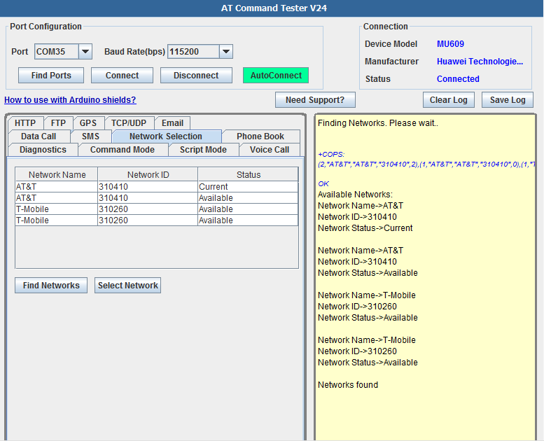
AT+COPS=?
+COPS: (2,”AT&T”,”AT&T”,”310410″,2),(1,”AT&T”,”AT&T”,”310410″,0),(1,”T-Mobile”,”T-Mobile”,”310260″,0),(1,”T-Mobile”,”T-Mobile”,”310260″,2),,(0,1,2,3,4),(0,1,2)
OK
Available Networks:
Network Name->AT&T
Network ID->310410
Network Status->Current
Network Name->AT&T
Network ID->310410
Network Status->Available
Network Name->T-Mobile
Network ID->310260
Network Status->Available
Network Name->T-Mobile
Network ID->310260
Network Status->Available
Networks found
How to test SMS?
AT Command Tester has an easy to use interface to send and read SMS messages. Currently ony ‘Text Mode’ is supported, “PDU Mode’ will soon be added.
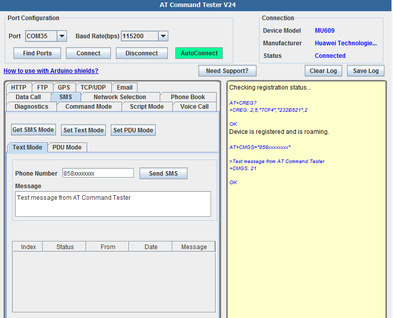
Checking registration status...
AT+CREG?
+CREG: 2,5,”7CF4″,”232B521″,2
OK
Device is registered and is roaming.
AT+CMGS=”858xxxxxxxx”
>Test message from AT Command Tester
+CMGS: 21
OK
How to setup TCP/UDP connection?
Huawei modules have embedded TCP/UDP stack. This lets us create IP connections which are needed for common applications like connecting to a remote server, email, FTP, HTTP etc.
In the TCP/UDP tab of the AT Command Tester, you can easily test TCP connections.
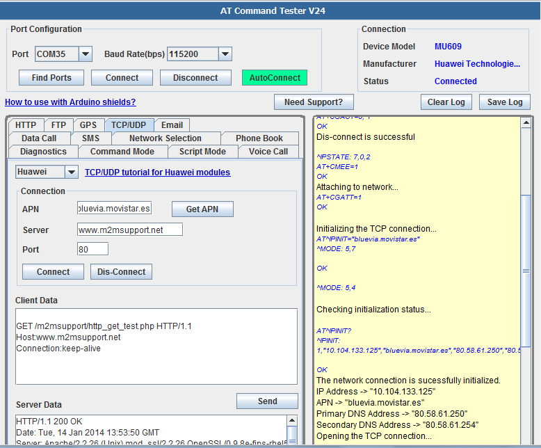
TCP Connection
Up to five TCP or UDP connection links can be setup at a time. First IP initialization uses the APN information to create a network connection. Once the IP is initialized, a successful IP address is avilable. Once the IP is initialized, a connection to a remote server to a specific port can be made.
Checking registration status...
AT+CREG?
+CREG: 2,5,”7CF4″,”232B521″,2
OK
Device is registered and is roaming.
Checking if device is already connected…
AT+CGACT?
+CGACT: 1,1
+CGACT: 15,0
OK
Disconnected profile 1
AT+CGACT=0, 1
OK
Dis-connect is successful
^IPSTATE: 7,0,2
AT+CMEE=1
OK
Attaching to network…
AT+CGATT=1
OK
Initializing the IP connection…
AT^IPINIT=”bluevia.movistar.es”
^MODE: 5,7
OK
^MODE: 5,4
Checking initialization status…
AT^IPINIT?
^IPINIT: 1,”10.104.133.125″,”bluevia.movistar.es”,”80.58.61.250″,”80.58.61.254″
OK
The network connection is sucessfully initialized.
IP Address -> “10.104.133.125”
APN -> “bluevia.movistar.es”
Primary DNS Address -> “80.58.61.250”
Secondary DNS Address -> “80.58.61.254”
Opening the TCP connection…
AT^IPOPEN=1,”TCP”,”www.m2msupport.net”,80
OK
AT^IPOPEN?
^IPOPEN: 1,”TCP”,39855,”74.124.194.252″,80,3,1220
OK
Following connections are opened,
Link ID-> 1
Type->”TCP”
Local Port->39855
Remote IP->”74.124.194.252″
Remote Port->80
SIO Port>3
MSS Port->1220
AT^IPOPEN?
^IPOPEN: 1,”TCP”,39855,”74.124.194.252″,80,3,1220
OK
Following connections are opened,
Link ID-> 1
Type->”TCP”
Local Port->39855
Remote IP->”74.124.194.252″
Remote Port->80
SIO Port>3
MSS Port->1220
Sending TCP data
How to send data to remote server?
Once an IP connection is established, you can use TCP or UDP to connect to a remote server. You can then send the client data using the AT Command Tester. In the above, example, the device is connected to HTTP port (80) of http://m2msupport.net. It then sends HTTP formatted message to the server over the TCP/IP connection. It gets successful response back from the server which is also a HTTP formatted message. When you input messages in the ‘Client Data’ text box, please check the appropriate formatting(newline) of the intended application.
AT^IPSEND=1,"

GET /m2msupport/http_get_test.php HTTP/1.1

Host:www.m2msupport.net

Connection:keep-alive
”
^IPDATA: 1,416,HTTP/1.1 200 OK
Date: Tue, 14 Jan 2014 13:53:50 GMT
Server: Apache/2.2.26 (Unix) mod_ssl/2.2.26 OpenSSL/0.9.8e-fips-rhel5 DAV/2 mod_auth_passthrough/2.1 mod_bwlimited/1.4 FrontPage/5.0.2.2635
X-Powered-By: PHP/5.2.17
Keep-Alive: timeout=3, max=100
Connection: Keep-Alive
Transfer-Encoding: chunked
Content-Type: text/html; charset=utf-8
3a
Sucessful HTTP GET test. Data received from m2msupport.net
0
^IPSEND: 1
OK
^IPSTATE: 1,0,0
How to test GPS?
In the ‘GPS’ tab of AT Command Tester, the GPS feature of Huawei modules can be tested.
Huawei modules supports different kind of GPS modes such as standlone, MS-Assisted, MS-based and gpsOneXTRA. Use can set the specific mode. Once the ‘Start Positioning’ button is presssed, the module will acquire the GPS position. Based the the GPS mode configured, the acquisition could vary and could take up to a minute. Once the GPS position is available, GPS information (latitude, longitude, altitude) will be automatically populated in the corresponding fields. If the GPS information is available, the ‘Show Map’ button will open the Google maps in a browser with the avaialble GPS coordinates.
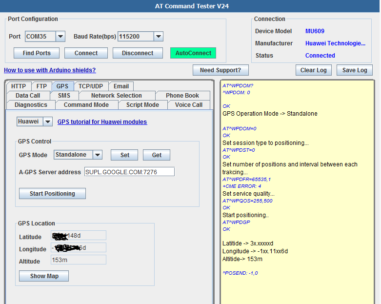
Set session type to positioning...

AT^WPDST=0
OK
Set number of positions and interval between each trakcing…
AT^WPDFR=65535,1
+CME ERROR: operation not supported
Set service quality…
AT^WPQOS=255,500
OK
Start positioning..
AT^WPDGP
OK
^POSITION: -1xx.xxxxxxd,3x.xxxxxxd,170m
Latitide -> 3x.xxxxxxd
Longitude -> -1xx.xxxxxxd
Altitide-> 170m
^POSEND: -1,0